Technical Dictionary
I. QUARTZ MATERIAL AND FREQUENCY CONTROL PRODUCTS
II.PIZEOELECTRICITY
III. TYPE OF QUARTZ CRYSTAL CUT
IV. MODE OF VIBRATION
V. FREQUENCY-TEMPERATURE CHARACTERISICS
VI.RESONANCE FREQUENCY
I. QUARTZ MATERIAL AND FREQUENCY CONTROL PRODUCTS
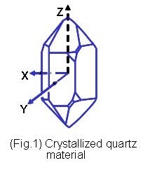
Quartz, a kind of crystallized Silicon Dioxide, SiO2, 32 symmetry group of trigonal system (Fig.1), exhibits piezoelectric property, which is the operating base of the electromechanical products. With its intrinstic high Q-value, the quartz based resonator and oscillator are the most wildly adopted as the reference signal source in circuitry for frequency control applications. Quartz frequency control products can be categorized into bulk acoustic wave application devices, such as crystals/resonators, monolithic crystal filters and clock oscillators, and surface accoustic wave application devices, such as SAW resonators and SAW filters. A piece of quartz crystal in a specific orientation cut, shape and dimensions is named crystal wafer (blank). Such a crystal wafer with two deposited electrodes on both sides and housed in a holder is a crystal unit (one-port resonator). By using the one-port resonators as impedance elements, crystal bandpass filters can be obtained. By incorporating the crystal resonator into a kind of electric circuit, one could get different kind of clock crystal oscillators (CXO), for example, Pierce Oscillator, Colpitts Oscillator, Simple Package Crystal Oscillator, Voltage Controlled Crystal Oscillatos, Temperature Compensated Crystal Oscillator, Oven Controlled Crystal Oscillator, and so on. Instead of bulk vibration of quartz crystals, a shorter wavelength (higher frequency) vibration can be achieved by surface wave propergation with inter-digital-transducer (IDT) electrodes on the surface of quartz material. This vibration mechanism can be used for resonator and filter applications
II.PIZEOELECTRICITY
The Silicon Dioxide atom is electrical natural in stable state. The electric dipole is along with silicon asix. Figure (2a) shows simplified two dimensional structure. When we apply an electric field along with dipole direction, with positive charged at the silicon side and negative charged at the oxygen side, the oxygen ions will repel to each other creating an induced electrical field to balance the system. The oxygen ions will toward to each other if we apply a negative charged and positive charged electric field to silicon and oxygen ions respectively. The oxygen ions will vibrate along horizontal direction in the same frequency as the alternative electric field along with vertical direction. The displacement of ions or the amplitude of vibration depends on the angle between the electrical field and the electric dipole of quartz. In practical three dimensional quartz crystals, electrical field is supplied by electriodes coated on the surface of quartz wafer. The orientatin of dipole can be decided through different kinds of cutting angles for quartz bar.

(Fig. 2) Simplified one dimensional piezoelectricity of SiO2
III. TYPE OF QUARTZ CRYSTAL CUT
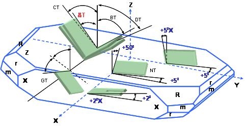
According to different cut angles to quartz bars, there are different kinds of quartz plates, for examples, AT-, BT-, CT-, DT-, NT-, GT- cut plates Different types of quartz cuts, indicated by a set of Euler angles, have different available elastic, piezoelectric and dielectric properties, which are the basic parameters for designing a quartz crystal device. The most often used Quartz-cut types are shown in﹝Fig. 3﹞ schematically.
﹝ Fig. 3 ﹞ Orientation angle of a Z-plate quartz crystal.
IV. MODE OF VIBRATION
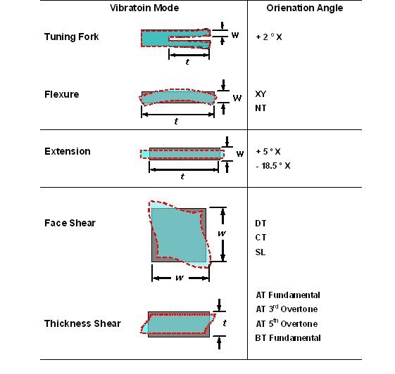
The vibration modes of the quartz crystal units are grouped into flexure, extension, face shear and thickness shear modes. The schematics of the vibration modes and the plate cuts usually used are listed in Table 1. Fundamental mode and overtone modes can be operated in any kinds of resonators. Fundamental mode is most often used, but for the thickness type devices the overtone modes are often used as well, as shown in (Table 1)
﹝ Table 1 ﹞ Vibration Mode and Cut Angle.
V. FREQUENCY-TEMPERATURECHARACTERISICS
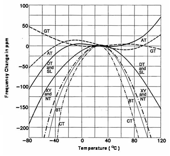
Most of the quartz products are used as an electrical circuit component for frequency selection and/or frequency control, so the frequency-temperature characteristic of the devices is the most important parameter. This parts per million (ppm) level stability of frequency-temperature characteristic is another merit of quartz frequency device that LCR discret component oscillation circuitry can not be achieved in mass-production scale. For the usually used quartz crystal cuts, their frequency-temperature characteristics are shown in (Fig. 4).
﹝ Fig.4 ﹞ Frequency-temperature characteristics of various quartz cuts.
AT-cut is the most popular crystal cut in the quartz devices for MHz applications. (Fig. 5) shows the orientation of AT plat from top view of + X-axis.
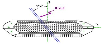
(Fig.5) Orientation of AT plat
(Fig. 6) shows the frequency-temperature characteristics of the AT-cut crystal operating in thickness-shear mode, with the cut angle deviation as a parameter. It is shown that AT-cut quartz has excellent frequency stability over a wide temperature range since the first-and second-order of the temperature coefficients go to zero in this range and the temperature coefficient is only dominated by a third-order function of the temperature deviation.
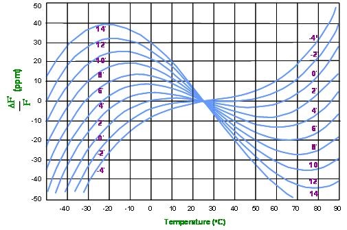
(Fig. 6) AT - cut frequency-temperature characteristics.
VI. RESONANCE FREQUENCY
In literatures and product descriptions, there are three pairs of resonance frequencies, i,e., the "series resonance frequency" and "parallel resonance frequency", ( fs and fp ) , the "resonance frequency" and "anti-resonance" frequency, ( fr and fa ), and the "maximum and minimum total admittance located" frequencies, ( fm and fn ). All of them can be obtained from the lumped equivalent circuit parameters as given in﹝Fig.9﹞The definitions and relationship of the resonance frequency pairs can be clearly expressed in a complex admittance diagram given in (Fig. 9).

﹝Fig.9﹞ Complex Admittance of Resonators
The series and parallel resonance frequencies, fs and fp are determined by taking the input electrical conductance (real part of the admittance) and resistance (real part of the electric input impedance) in maximum, respectively, as shown in (Fig. 9). The resonance frequency, fr and anti-resonance frequency, fa , are given by the two roots where the susceptance (imaginary part of the input electric admittance) equals to zero, as shown in (Fig. 9). The resonance frequency and anti-resonance frequency fr and fa are the frequencies of principal interest in two terminal applications. For evaluating the equivalent circuit of a resonator, however, the characteristic frequencies, fs and fp are more important. They are given by
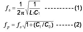
Where, C1and L1are the motional capacitance and motional inductance, respectively, and Co is the static capacitance appearing in shunt branch (Fig. 7).
Technical support
2003-2021 Shenzhen RenLux Crystal Co., Ltd 粤ICP备10224540号-1
Address:TCL building, Hi-tech park, Nanshan, Shenzhen, China Tel:+86-137-28697591 Fax:+86-755-27808183 E-mail: sales@renluxcrystal.com
